In oder to be able able to physically interact with the car it is running on, Android Automotive needs access to the in-vehicle networks (IVN). What these IVNs are and how Android handles the connection to them is subject of this article.
In-vehicle Networks
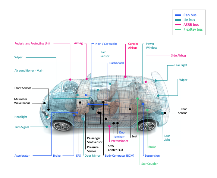
In-vehicle networks (IVN) build up the car’s internal nervous system and are responsible for the communication between the various electronically control units (ECU) as shown in the figure below
In order to gain access to or control over these ECUs, Android needs to have access to these IVNs. On of these IVN is the Controller Area Network that will be main focus point of this article.
Controller Area Network
The Controller Area Network (CAN) is a network designed to allow micro controllers and devices or generally ECUs to communicate with each other without the need for a host computer. The communication takes place on a peer-to-peer fashion. Before using CAN, the individual ECUs within cars were connected through individual cables using analog signals. With an increasing number of ECUs that added significant additional cost and weight to the car which let Bosch to start developing the CAN standard in 1986 to pose a solution to this problem. In 1991 the ISO-11898 standard was established. CAN replaces this old system by connecting each component with just a single uniform data line on which data is transmitted sequentially.
Nowadays the Controller Area Network can be found in road vehicles, hospitals, elevators and many more systems where a reliable communication is crucial.
Physical Architecture
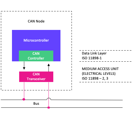
Data within the CAN is transmitted via two cables: CAN high and CAN low. Both data lines are either in a dominant state (representing a digital 0) or in a recessive state (representing a digital 1). The voltage of both data lines is typically at 2.5V during the recessive state and during the dominate state 3.5V (CAN high) and 1.5V (CAN low). In order to transfer data two or mode nodes are required. These nodes are set like seen below and consist of three main components.
Transceiver
Responsible for transmitting and receiving data as electrical signals. It is directly connected to both the CAN high and the CAN low data lines.
CAN controller
Responsible for transmitting/receiving data as serial bits to/from the transceiver and for transmitting/receiving data as CAN frames to/from the microcontroller.
Microcontroller
Responsible for processing received data and deciding on which data to transmit to the CAN bus.
Sending and requesting data
Within the CAN bus all participating nodes can send 4 types of frames. These frames include the data frame, the remote frame, the error frame and the overload frame. For us relevant are the data frame that allows transmitting of data and the remote with which data from an other node can be requested.
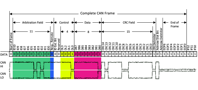
Both data and remote frame are preceded with the unique identifier mentioned before (the 11 bit arbitration field as seen below). This ID indicates the type of data that is transmitted. The following bit specifies whether the frame is a data frame (0) or a remote frame (1). In case of a remote frame, the node able to process the request will respond with the requested data by transmitting a data frame with the same ID.
The data length is defined by the last 4 control bits and ranges from 0 to 64 bits. Even if the control bits can be set to 15 the data size is limited to 64 bits by definition. Thus only short messages can be send with a single frame. The following 15 bits are reserved for the CRC that makes sure that no errors took place throughout the transmission. Once a node processed the frame sent, it will set the acknowledged bit to 1.
ID Arbitration
Since CAN is a multi master network there is no single instance that can decide which of the nodes is allowed to talk at a given point in time. So the question arises how this is determined eventually.
Every data frame transmitted by a node is preceded with a unique identifier that at the same time also reflects the priority of the to be transmitted message. This id is used in the arbitration process. On simple terms a message with a lower ID has priority over a message with a higher ID meaning that the message with the lowest ID will always be transmitted first.
To understand how this works within the CAN network, we have to first understand how data is transmitted on the physical layer: The ISO standard differentiates between a “recessive” and a “dominant” state on the data line where a recessive state represents a logical 1 and a dominant state a logical 0. Within the CAN network a logical 0 will always dominate a logical 1.
Now let us assume that two nodes are transmitting a frame of data at the same time. Node 1 (N1) transmits a frame with ID 127 and node 2 (N2) transmits a frame with ID 128.
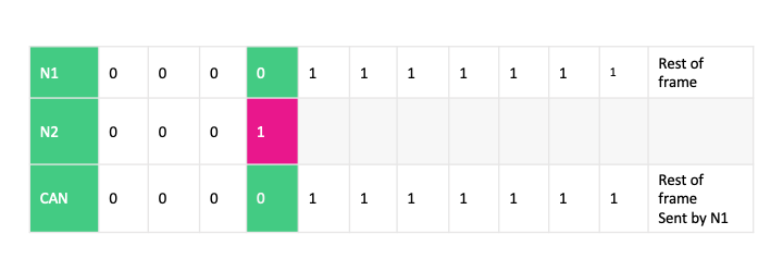
Each bit of the frame is sent at the same time by both N1 and N2. Simultaneously, both nodes are reading the actual value that has been transmitted on the bus. Looking at the table above we can see that N2 transmits a 1 at the forth bit where N1 transmits a 0. N2 will check the can bus and (since a 0 dominates a 1) reads a 0. This tells N2 that another node is currently transmitting a frame with a lower ID and higher priority. Thus N2 will immediately stop transmitting. N1 on the other side gets back a 0 from the can bus which equals the bit it transmitted and will thus continue transmitting. By the end of the 11 arbitration bits, N1 will be the only winner. It will gain the first access, without any bit loss or delay. N2 will respond to failure to gain bus access by automatically switching to receive mode; it then repeats the transmission attempt as soon as the bus is free again.
The Hardware Abstraction Layer (HAL) plays the most important role here. It acts as a separation layer between the physical hardware devices and the Android Framework by simply abstracting their functionality into software interfaces.
Before the introduction of Android 8 these interfaces where simply defined as C header files. The hardware specific implementation was then implemented using C/C++. Communication between the Android Framework code writing in Java and the C++ code took place using JNI. The major disadvantage of this approach was that the header files were not versioned which required drivers to be rewritten whenever an interface definition within the HAL changes, eventually slowing down the Android upgrade process.
To solve this problem, Google introduced the HAL Interface Definition Language (HIDL) with the release of Android 8.0.
HIDL
The HAL Interface Definition Language (HIDL) is used within the Hardware Abstraction Layer to define the interfaces describing the individual hardware devices that are used in combination Android. The main advantage HIDL has over the previous approach with using header files is that HIDL interfaces are backwards compatible. To achieve that, each change within the interface is signed, published and versioned. Once published, a specific version of the interface is immutable. Implementations of old versions are expected to work as long as the signature of that interface is supported by the futures versions of Android.
The implementation of HIDL interfaces typically takes place within a separate process so that the system service talks to the hardware driver implementation using Binder, Android’s build-in inter-process communication (IPC) mechanism. One exception is the passthrough implementation for compatibility with already existing legacy HAL implementations that instead runs within the system service.
The difference between the legacy HAL and HIDL-based HAL definition can be found below
struct vibrator_device;
typedef struct vibrator_device {
  struct hw_device_t common;
  //...
  int (*vibrator_on)(struct vibrator_device* vibradev, unsigned int timeout_ms);

  int (*vibrator_off)(struct vibrator_device* vibradev);
  //...
} vibrator_device_t;
hardware/libhardware/include/hardware/vibrator.h
interface IVibrator {
  //...
  on(uint32_t timeoutMs) generates (Status vibratorOnRet);

  off() generates (Status vibratorOffRet);
  //...
};
hardware/interfaces/vibrator/1.0/IVibrator.hal
Android supports a wide selection of hardware devices responsible for audio output, reading sensor data and much more. For the connection to the car’s IVNs Android Automotive includes the Vehicle HAL.
The Vehicle HAL (VHAL)
The Vehicle HAL (VHAL) is one of the many HALs available within Android (Automotive). It is, as mandated by Android 8.0, defined in HIDL. It describes the communication with the in-vehicle networks (IVN) using the functions shown below. Data is transferred using VehiclePropValues.
interface IVehicle {
  //...
  get(VehiclePropValue requestedPropValue) generates (StatusCode status, VehiclePropValue propValue);

  set(VehiclePropValue propValue) generates (StatusCode status);

  subscribe(IVehicleCallback callback, vec<SubscribeOptions> options) generates (StatusCode status);

  unsubscribe(IVehicleCallback callback, int32_t propId) generates (StatusCode status);
  //...
}
hardware/interfaces/automotive/vehicle/2.0/IVehicle.hal
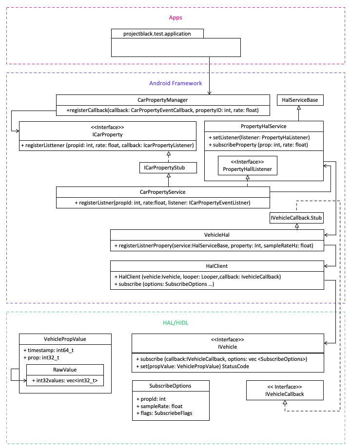
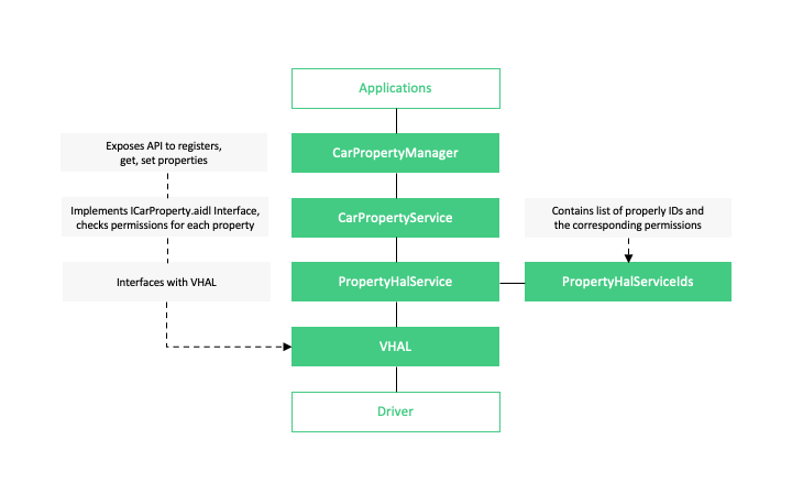
The VHAL is made available to the application layer by the CarPropertyManager that exposes the API to register, get and set VehiclePropValues. An overview on the communication stack between the hardware specific driver implementation and the application layer can be found below.
It is worth noting that Android does not specify the data transfer standard or the IVN to be used. This has to be specified within the implementation of the VHAL. This allows not only a connection to the CAN bus but also to other car internal networks such as the Local Interconnect Network (LIN) or different future in-vehicle communication standards.
Detailed Flow and Responsibilities
For a more detailed understanding of the components involved please refer to the abbreviate class diagram below. It includes all classes and interfaces relevant for providing access to the in-vehicle network. As mentioned previously, the CarPropertyManager plays the main role in proving the application layer access to the VHAL.
When subscribing to a vehicle property (VehiclePropValue) the following steps take place within the Android operating system:
-
Invoke CarPropertyManager#registerCallback in order to register to a vehicle property by providing the CarPropertyEventCallback, the propertyId id of the vehicle property and the rate (update frequency)
-
CarPropertyManager talks to the CarPropertyService using Binder and via ICarProperty#registerListener and provides an ICarPropertyEventListener as callback
-
CarPropertyService checks if the required permission is granted. If that is the case safes the callback in a map, associated with the property id. It then passes on the subscription to the PropertyHalService using PropertyHalService#setListener and PropertyHalService#subscribeProperty.
-
PropertyHalService verifies that the to be subscribed property id exists and validates the update frequency, then passes on the subscription to VehicleHal#subscribeProperty
-
VehicleHal checks if the property is actually subscribable and if that is the case passes it on to HalClient#subscribe
-
HalClient then talks directly to IVehicle